Understanding that 2-stage workflow is the fastest way to understand the machine itself, because every spec on a मोड़ने की मशीन exists to turn an accurate flat blank into an accurate 3-dimensional part. This explainer walks the full path: what the machine family includes, how blanks move from cutting to forming, how the 3 bending methods differ, the math that predicts where metal folds, and how the common materials behave under the punch.
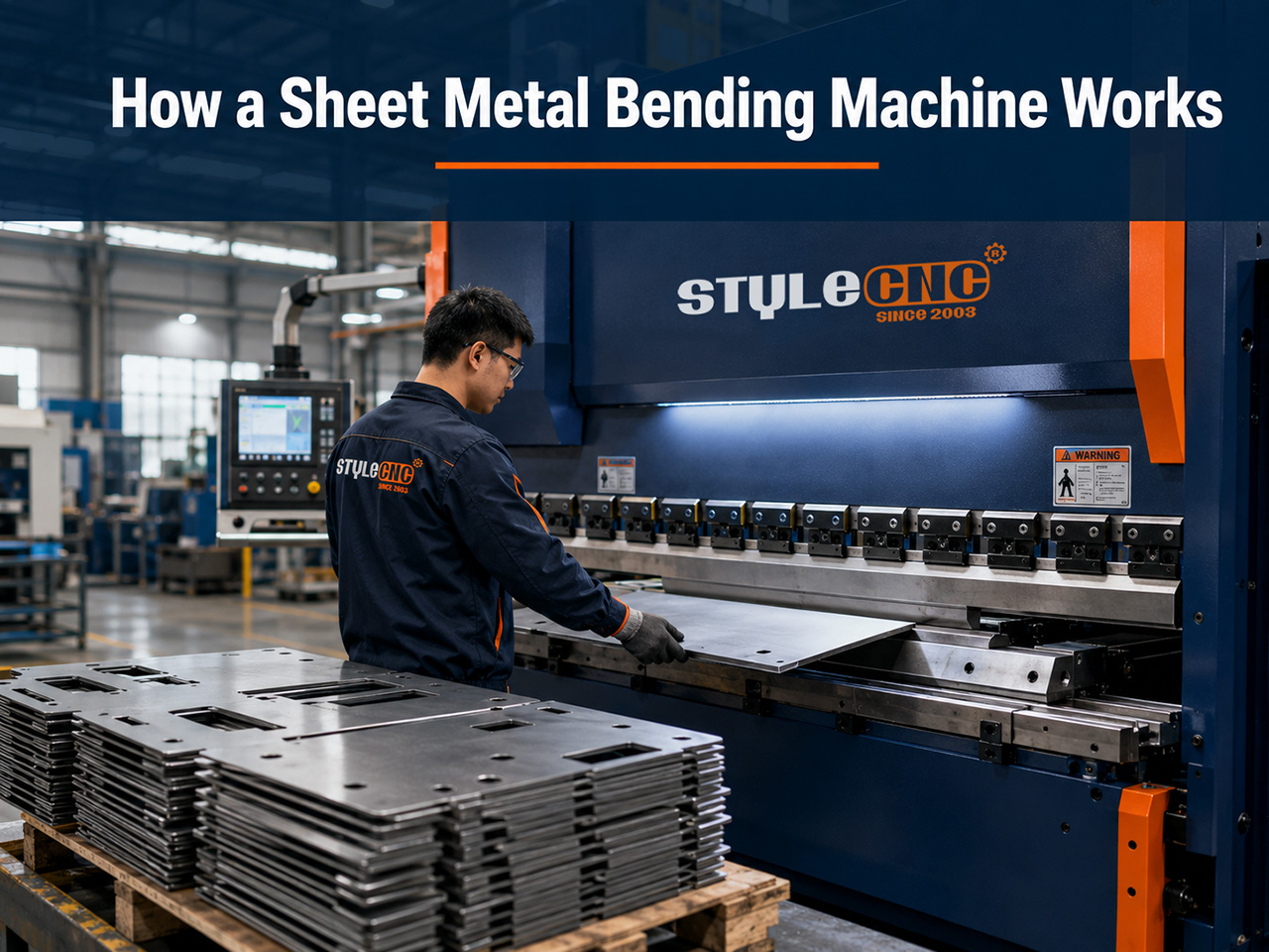
What Counts as a Sheet Metal Bending Machine
The term covers a family rather than a single machine. The press brake is the workhorse, driving a punch into a V die along a long bed. Folding machines and sheet metal folders clamp the blank and swing a beam to fold the edge upward, which keeps the sheet flat on a table and suits large panels handled by one operator.
The box and pan brake adds segmented fingers to the clamping beam so formed sides can clear the tooling, which is what lets it form all 4 walls of a box or tray. Plate bending machines take a different approach entirely, curving thick plate between rolls rather than creasing it at a line.
Which machine a shop reaches for depends on the part. Long creased profiles favor the press brake, oversized panels favor the folder, enclosures favor segmented tooling, and cylinders favor rolls. Most fabrication shops end up with a press brake first, because it covers the widest share of bent parts with one investment.
The press brake versus folder decision deserves one more sentence of nuance, because the 2 handle the sheet in opposite ways. A ब्रेक दबाये asks the operator to support the blank while the flange swings up, which becomes a 2-person job on large thin panels that flex under their own weight. A folder holds the panel flat on its table and moves only the folding beam, so a single operator can form panels a press brake crew would struggle with. Shops running architectural cladding or HVAC ductwork often justify a folder purely on the labor arithmetic.
The Cut-Then-Bend Workflow
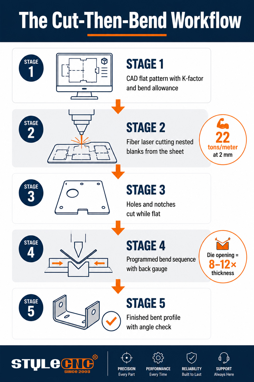
Production bending starts before the bending machine. The flat blank is cut to a calculated developed length, holes and notches are cut while the sheet is still flat, and only then does the part reach the brake. Cutting features flat is dramatically cheaper and more accurate than adding them after forming.
Blank accuracy sets the ceiling for bend accuracy. A फाइबर लेजर कटिंग मशीन बेंडिंग लाइन को फीड कर रही है delivers blanks with edge quality and dimensional consistency that a bending controller can trust, which is why so many bending problems are actually cutting problems in disguise. Shops working thicker plate often run metal laser cutting machines for blank preparation या एक सीएनसी प्लाज्मा कटर upstream, trading some edge finish for speed on heavy sections.
Operators frame the handoff in practical questions: will this blank's burr side face the die and mark the part, or did the cutting program account for grain direction so the bend does not crack? Those details travel with the blank, and the shops that manage them at the cutting stage bend with far less scrap.
Batch flow ties the 2 stages together economically. Nesting software packs dozens of developed flat patterns onto each sheet before cutting, so the bending cell receives blanks in job order with minimal material waste. When the cutting and bending programs come from the same CAD model, the developed lengths, hole positions, and bend lines agree by construction, and the 1st article usually passes inspection on the 1st try.
The bending stage itself follows a programmed sequence. The controller orders the bends so earlier flanges never collide with the tooling, the back gauge positions the blank for each stroke, and the operator flips or rotates the part between bends as the simulation dictates. A 4-bend enclosure might take under a minute on a well-sequenced program and 3 times that on a poorly planned one.
Air Bending vs Bottoming vs Coining
All 3 methods use the same punch-and-die geometry; what changes is how deep the punch travels and how much force it applies. The choice drives tonnage requirements, tooling costs, and how much springback the controller must outsmart:
| फ़ैक्टर | हवा का झुकना | नीचे का | गढ़ने | माप |
|---|---|---|---|---|
| Punch travel | Stops short of the die bottom | Presses sheet fully into the die | Stamps punch tip into the material | Punch depth relative to die V opening |
| Tonnage required | Lowest of the 3 methods | Roughly 3 to 5 times air bending | Up to 10 times air bending | Tons per meter from thickness and die width |
| स्प्रिंग बेक | Largest; controller overbends to compensate | Reduced; die contact sets the angle | Nearly eliminated under stamping force | Degrees of elastic recovery after punch lift |
| Tooling flexibility | One tool set forms many angles | One die per target angle | Dedicated tooling per part | Number of tool changes across your part mix |
| सबसे अच्छा उपयोग | General fabrication, mixed runs | Tight-tolerance repeat parts | Critical angles on thin sheet | Share of parts needing under half a degree |
Springback is the behavior underneath the whole comparison. Every metal recovers elastically when the punch lifts, opening the bend slightly. Air bending accepts that recovery and overbends to compensate, which is why it dominates modern shops: one tool set, moderate tonnage, and a controller that does the compensation math per material.
Bend Allowance, K-Factor, and a Worked Example
Metal stretches on the outside of a bend and compresses on the inside, and somewhere between the 2 surfaces sits a neutral axis that keeps its original length. The K-factor locates that axis as a fraction of thickness, typically around 0.3 to 0.5, and the bend allowance uses it to calculate how much flat material each bend consumes.
The practical numbers that come out of this math:
• Bend allowance sets the developed flat length, so the cutting program depends on it before the brake ever touches the part.
• A common rule places minimum inside bend radius at about one material thickness for mild steel to avoid cracking.
• Die opening width is usually 8 to 12 times material thickness, and widening the die lowers the tonnage needed.
A worked tonnage example makes the relationship concrete. Bending 2 mm mild steel over a 16 mm V die requires roughly 22 tons per meter of bend length, so a 1.2 meter flange needs about 27 tons. Move to 3 mm over a 24 mm die and the requirement climbs near 33 tons per meter. The pattern to remember: tonnage rises with the square of thickness, which is why a machine sized for 2 mm work cannot casually take on 6 mm plate.
Printed tonnage charts on the machine frame encode exactly this math for every standard die opening, and experienced operators check them by habit rather than memory. The chart also reveals the escape route when a job exceeds the machine: widening the die drops the required tonnage substantially, at the cost of a larger inside radius and a wider minimum flange. Whether that trade is acceptable depends on the drawing, which is why the tonnage conversation always ends back at the part print.
How the Common Materials Behave
नरम इस्पात
Mild steel is the baseline the tonnage charts assume: predictable springback of a degree or two, forgiving of tight radii, and consistent from sheet to sheet. Most steel fabrication applications bend without drama when the blank is clean and the grain direction is respected.
स्टेनलेस स्टील
Stainless demands roughly 50 percent more tonnage than mild steel at equal thickness and springs back further, often 2 to 3 degrees. It also work-hardens as it forms, so a bend attempted twice in the same place risks cracking. Program the overbend correctly the 1st time. On finish-critical stainless, protective film and polished dies earn their cost, because die marks that would sand out of mild steel become permanent scars on a brushed surface.
एल्युमीनियम
Aluminum forms with less force but punishes tight radii, especially in harder tempers where a radius under 1.5 times thickness invites cracking along the bend line. Springback runs larger than mild steel despite the lower force. The alloys common in aluminum fabrication applications each carry their own minimum radius, and the soft tempers bend far more forgivingly than the structural ones.
Common Bending Defects and Their Causes
⦿ Cracking along the bend line: radius too tight for the material or bend placed parallel to the grain direction.
⦿ Inconsistent angles across a batch: material thickness variation between sheets, not machine error.
⦿ Under-formed center on long bends: ram deflection without crowning compensation.
⦿ Die marks on visible surfaces: worn tooling or missing protective film on finish-critical parts.
⦿ Flanges out of dimension: bend allowance calculated with the wrong K-factor, so the blank was cut to the wrong developed length.
Workflow Checklist Before the 1st Bend
☑ Confirm the developed flat length was calculated with the K-factor your material actually exhibits.
☑ Cut all holes and notches while the sheet is flat, keeping critical holes at least 2.5 times thickness from bend lines.
☑ Orient bends across the grain direction where the part allows it.
☑ Verify die opening is 8 to 12 times thickness and tonnage is within the machine's comfortable range.
☑ Run one 1st article and measure angle and flange length before committing the batch.
Start the Workflow at the Cutting Table
Accurate bending begins with accurate blanks. Explore fiber laser cutting machines built to feed bending lines and get a free quote matched to your materials, thicknesses, and daily part volume.